Klik hier om in het nederlands te lezen
English
12Urenloop is an annual running race at the Sint-Pieters square in Ghent. Participating student association teams run a relay race for 12 hours, trying to complete as many laps as possible. Each team is assigned one baton, so they can only have one runner on the track at a time.
Zeus WPI has been doing the lap counting at the 12Urenloop for a while: first through a manual counting system where runners’ bib numbers were entered by hand, then from 2011 onwards with an automatic counting system based on bluetooth modules in the batons. For more background on the historical hardware and software, you can read the 2011 blog post.
Between 2019 and 2022 the entire stack was overhauled, with more modern hardware, an estimated position of runners shown on the website, and extensive redundancy, fault tolerance and monitoring. There’s also a detailed blog post about that.
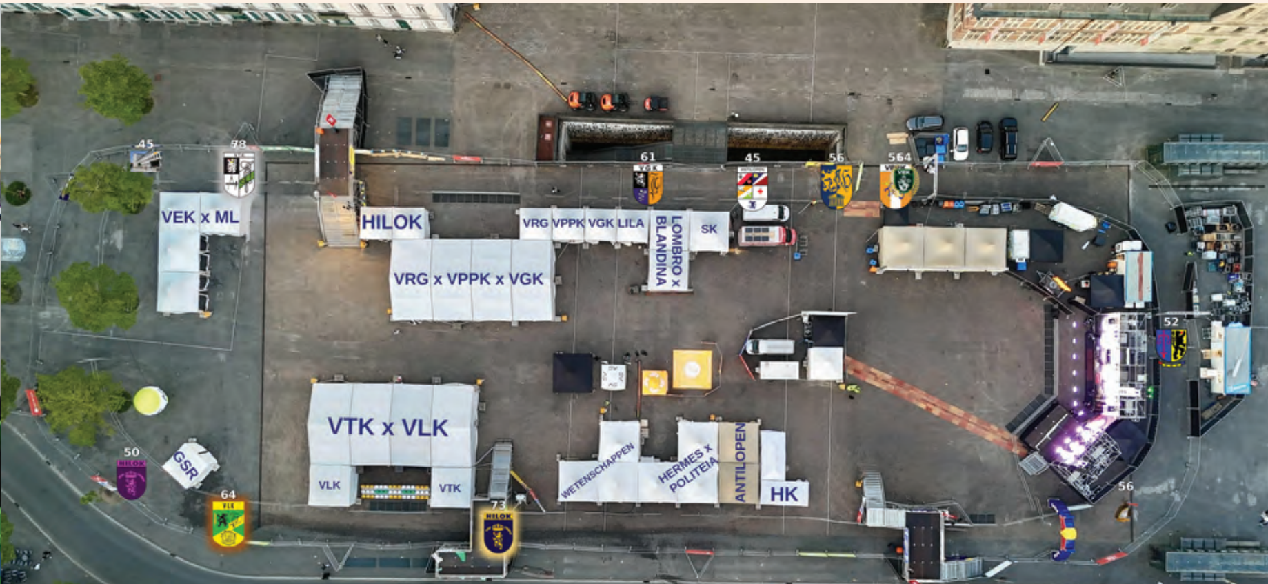
The live tracking site on 12urenloop.be, showing the associations’ team logos estimated positions moving on the track
What is UWB?
Around the end of October this year I saw some online demos of UltraWideBand hardware using easily obtainable and relatively cheap hardware. UltraWideBand is a radio communication standard focused on centimeter-level localization of transmitters/receivers. This is possible partly because it uses a large chunk of the radio spectrum (500 MHz), which makes it very good at ignoring signal reflections. That means it can identify the very start of a received packet. If you pair that with a clock accurate to the picosecond level, and compare the time a packet was sent with the time it was received, you can calculate how long that packet was in the air (at the speed of light) between transmitter and receiver. Multiply that time by the speed of light and you get the distance between transmitter and receiver. If you can measure that distance to a moving UWB transmitter (tag) from multiple UWB transmitters at fixed positions, you can calculate the tag’s position. This is the same principle GPS uses, just on a smaller scale.
This technology is used in, among other things, iPhones and AirTags, to show the distance and direction to an AirTag. It’s also used in newer car keys that unlock the car when you get close, because a UWB signal can be encrypted and is therefore resistant to relay attacks.
What does this tech make possible?
There had already been talk since 2021 about using UWB at the 12Urenloop, because it offers some major advantages:
-
Exact position measurement: the current bluetooth system gives a good estimate of progress on the circuit (by calculating speed), but no actual position measurements.
-
With positioning, a lap can be counted at the exact moment someone crosses the start line. This isn’t possible with existing RFID systems used for running races, because at the 12Urenloop there’s a start line per team (at each association’s tent).
-
More statistics about individual runners: maximum/minimum speed, cornering speed, etc.
-
A cleaner signal, since there’s a lot of noise from bluetooth signals coming from the hundreds/thousands of spectators.
What you build yourself is usually cheaper
Ready-made RTLS (real-time location system) solutions exist, with all the hardware and software you need, but these are outside the budget of a race organized by students (a starter kit from the Ghent-based Pozyx already costs around 5000 euros).
In recent years the price of UWB modules has dropped sharply, to around 19-25 euros per module for officially packaged Qorvo modules (used by Pozyx and interoperable with Apple’s U1 chip), and even as low as 12 euros for aftermarket packaged modules (clones) with an integrated microcontroller.
So it seemed like a good time to explore how feasible and useful a UWB system could be at the 12Urenloop.
On closer inspection, there’s practically no open-source software that supports positioning multiple tags, at least for microcontrollers outside the handful Qorvo supports. Almost all available code focuses on tracking a single tag with multiple anchors, since that’s also a lot simpler. When there are multiple tags and anchors, all UWB modules need to coordinate when they’re allowed to transmit; all communication happens over a single channel, so nothing can talk over anything else. Synchronization between modules needs to be within a few milliseconds to achieve a measurement rate of 1-10 times per second per tag.
With that in mind, we ordered 5 DWM3000 UWB modules so we could build a setup with 3 anchors at fixed positions, and 2 tags whose position we determine.
To drive the UWB modules we chose the ESP32-WROOM, because they’re cheap (4 euros), have bluetooth and wifi, and were already available in our basement clubroom. The code was written in the Arduino framework, so it’s also easy to port to other microcontrollers.
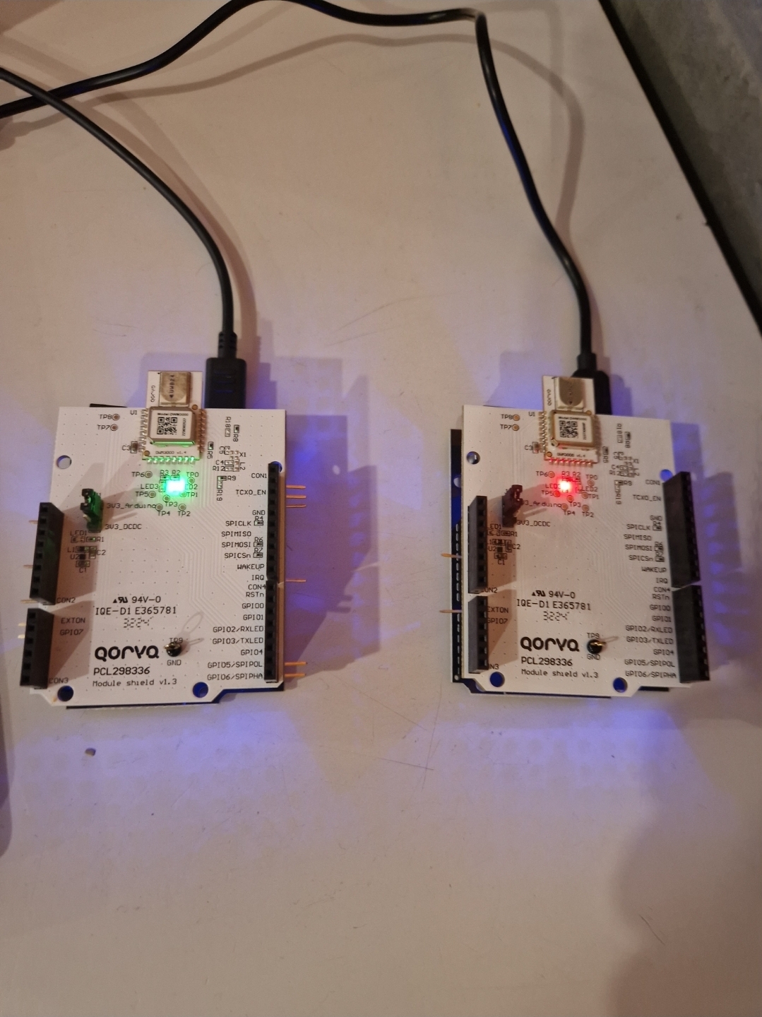
Two DWM3000 devboard shields on a Wemos D1 Uno (ESP32-WROOM board with arduino Uno form factor)
Tuning & testing
The DW3000 chipset on the UWB module is controlled over SPI, by reading and writing hundreds of registers and about a dozen commands. Qorvo (the manufacturer) provides an SDK to make certain functions easier to implement, but it only works for a handful of microcontrollers such as the NRF52 and STM32 families — not Espressif chips. Fortunately there’s a port of the driver library to the Arduino framework.
The focus of the first few weeks was to determine whether the DWM3000 UWB module was suitable for use at the 12Urenloop: is the module’s range far enough (the goal was at least 30 meters), is the measured distance accurate enough, and how often can you measure position when there are 15 tags (one per runner) on the circuit?
After a lot of tuning of registers for the radio frame structure and transmit power, we managed to measure distance up to about 50 meters. With larger antennas on the anchors, this could probably be improved a lot further. Range does get worse when there’s no line of sight between the two modules, or when there’s a lot of metal nearby (both cause reflections of the radio signal).
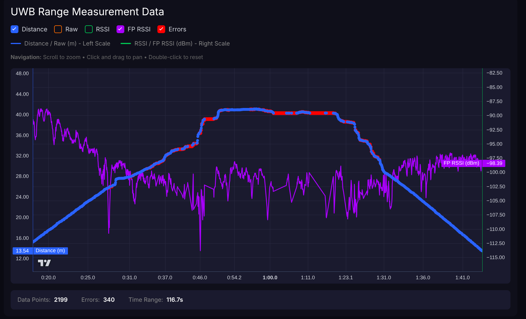
A graph of distance and RSSI values of a line of sight range test in open field, walking 40 meters forward, turning around a few times and coming back.
After a bit of calibration we managed to measure distance between 2 modules with about 2 centimeters of tolerance within 5 meters. At longer distances, a bit more calibration per module is needed to stay accurate, after that it can stay between 10 centimeters of tolerance using a double sided ranging scheme (both UWB modules measure the distance to each other).
After these initial results, it was time to do a positioning test: 2 anchor modules were placed in the corner of our clubroom, and the third, tag module took turns measuring its distance to each anchor. The anchors send those distances to the tag over wifi via MQTT.
The triangulated position was visualized in real time by a dashboard built with Bevy.
Left is the triangulation application’s live output, Right is our club room’s webcam
To get this system working with 2 tags at high speed, without anyone talking over each other on the radio channel, synchronization is needed between anchors: they need to know when it’s their turn to send out a message, and when they need to wait so the rest can take their measurements. In the implementation, this works through a clock shared between all anchors: each anchor is assigned a time slot within an interval. With an interval of 1 second and time slots of 10 milliseconds, for example, you can make 100 distance measurements per second.
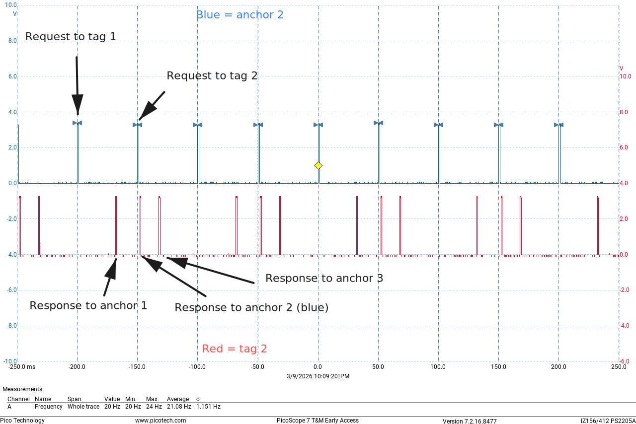
Oscilloscope trace of an anchor (blue) and tag (red)’s transmit status (on or off), you can see the anchor is sending a ranging request to 2 tags, taking turns every assigned time slot. The red blip you see directly under each blue blip is the response of the red tag to the request from the blue anchor. the other red blips are responses to the other 2 anchors in the system, they are also sending out ranging requests in their assigned timeslots
Distribution of the clock (a count of ticks on the UWB chip) happens through the existing UWB messages. Every time a message is sent between an anchor and a tag, they exchange their clock values, and the highest clock value is adopted by both parties (monotonically increasing clock).
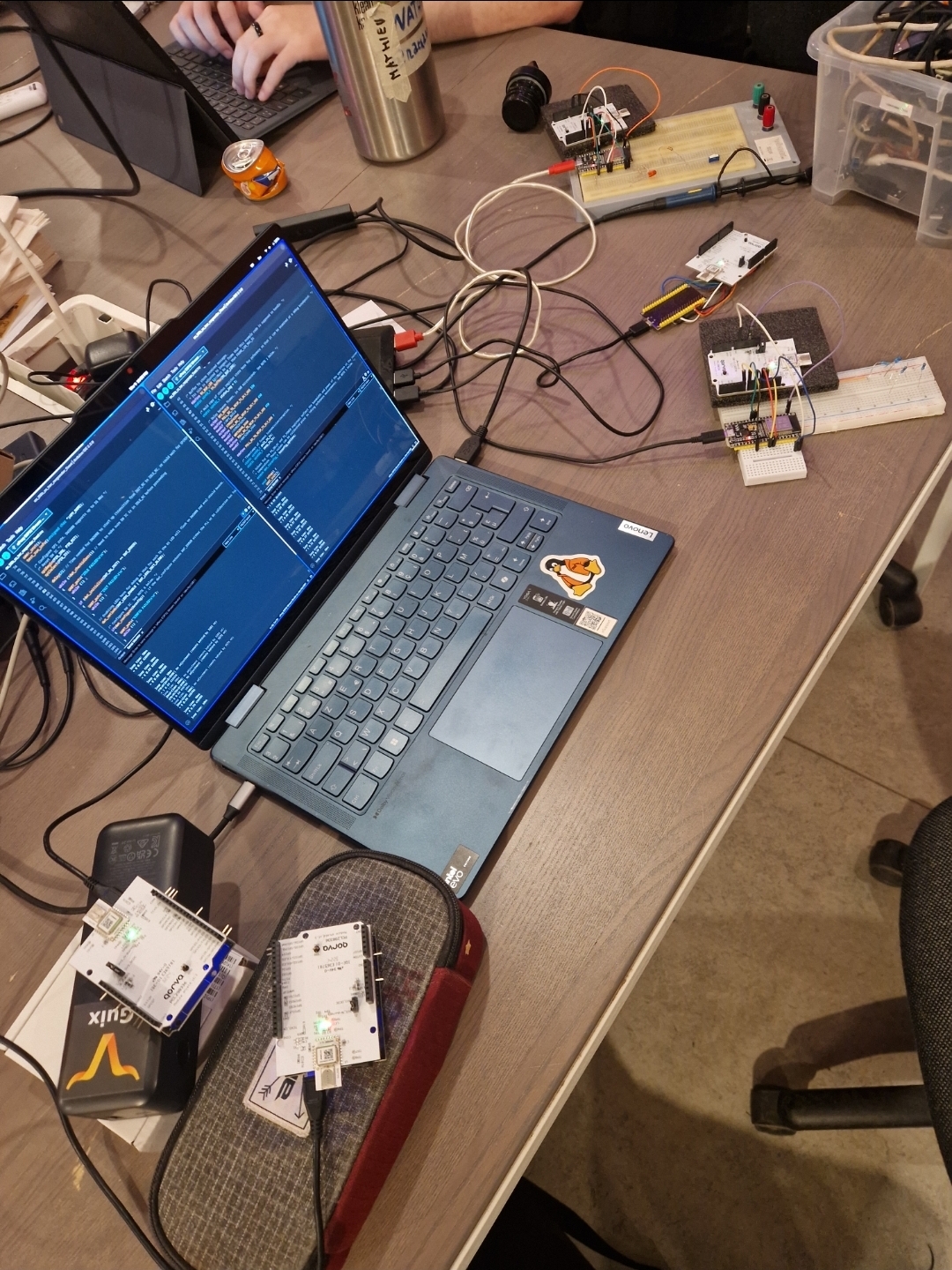
The crazy setup with 5 UWB modules hooked up to a single laptop, we didn’t have an easy way to connect all UWB modules to one of our ESP32’s
Here’s a demo under ideal conditions with 3 anchors and 2 tags: measurements are coordinated at a rate of 60 Hz, which comes out to 60 / 2 / 3 = 10 position measurements per second. In theory, this timing could therefore update the position of 20 tags once per second.
The graphics from the triangulation application was overlayed on a video recording of the test for analysis, some miscalibration remains here in certain regions
To aggregate all these measurements in real time at the 12Urenloop and build a live-tracking visualization, some more software is needed. The current system uses 7 stations with Raspberry Pis spread around the circuit, connected via Ethernet. To test this prototype at this year’s edition of the 12Urenloop, the 3 anchors were connected to the Raspberry Pis via USB. A publisher script reads the measurement results from the anchors and sends those messages to a central RabbitMQ server in our control room (container). The real-time Bevy dashboard reads all the messages and performs all the triangulation logic, which lap counting can then be based on.
Supporting more anchors
It’s estimated that 7-10 anchors will be needed to position tags across the entire 12Urenloop circuit, but that means at most 3 anchors will ever be within range of a tag at the same time. If every anchor still needed the channel to contact every tag individually, the measurement rate would drop quickly as the number of anchors grows.
This can be solved by reusing time slots between anchors that can never be in range of a tag at the same time.
With that, the proof of concept is complete. The system was tested on one corner of the 12Urenloop circuit the day before the race. The results were (after calibration) good enough in quality to support accurate tracking.
In order to actually take this system in use, the tags will need to be integrated into the batons where the current bluetooth system now sits, and more extensive power and reliability measurements will need to be taken.
The repository with all the code can be found on Github.
A big thanks to 12Urenloop and everyone at Zeus that helped.
You can contact me at uwb@robinp.be .
Nederlands
De 12urenloop is een jaarlijkse loopwedstrijd op het Sint-Pietersplein in Gent. De deelnemende studentenverenigingen lopen in een estafetterace 12 uur zoveel mogelijk rondjes. Elk team krijgt één baton (doorgeefstok) toegekend, dus ze kunnen maar één loper tegelijk hebben.
Zeus doet al even het tellen op de 12urenloop: eerst via een manueel telsysteem waarbij de rugnummers van de lopers worden ingegeven, dan vanaf 2011 met een automatisch telsysteem dat werkt via bluetooth-modules in de batons. Voor de rest van de context qua de historische hardware en software kan je de blogpost uit 2011 lezen.
In 2019-2022 werd de hele stack opnieuw vernieuwd, met modernere hardware, een ingeschatte positie van de lopers op de website, en uitgebreide redundancy, fault-tolerance en monitoring. Ook hier is een gedetaileerde blogpost over geschreven.
Wat is UWB?
Rond eind oktober dit jaar zag ik online enkele demo’s van UltraWideBand hardware met gemakkelijk te verkrijgen en relatief goedkope hardware. UltraWideBand is een radiocommunicatie-standaard gefocust op centimeter-level localisatie van zenders of ontvangers. Dit kan o.a. omdat het een groot deel van het radiospectrum (500 Mhz) gebruikt en zo heel goed is in het negeren van reflecties van een signaal. Het kan dus gemakkelijk het begin van een ontvangen packet identificeren. Als je dat paart met een klok die accuraat is op picoseconden-niveau en je de verzendtijd van een pakket vergelijkt met de tijd van ontvangen, dan kan je berekenen hoe lang dat pakket in de lucht is geweest (aan de lichtsnelheid) tussen zender en ontvanger. Vermenigvuldig die tijd met de lichtsnelheid en je krijgt de afstand tussen zender en ontvanger. Als je die afstand tot een bewegende UWB zender (Tag) kan meten vanaf meerdere UWB zenders op een vaste positie, kan je de positie van de tag berekenen. Dit is hetzelfde principe dat GPS gebruikt, maar op een kleinere schaal.
Deze technologie wordt o.a. gebruikt in Iphones en Airtags; om de afstand en richting naar de Airtag te tonen. Ook in nieuwe autosleutels die de auto openen als je dichtbij komt, omdat een UWB signaal geëncrypteerd kan zijn en zo resistant is tegen relay aanvallen.
Wat maakt deze technologie mogelijk?
Er werd sinds 2021 al gepraat over UWB gebruiken bij de 12Urenloop, want het biedt enkele grote voordelen:
-
Exacte positiemeting: Het huidige bluetooth-systeem geeft een goede inschatting van de voortgang op het circuit (door de snelheid te berekenen), maar geen positiemetingen.
-
Met positionering kan een ronde geteld op het exacte moment dat iemand over de startlijn gaat, Dit lukt niet met bestaande RFID systemen die voor loopraces worden gebruikt, want bij 12Urenloop is er een startlijn per team (aan de tent van elk team van verenigingen).
-
Meer statistieken over individuele lopers: Maximum/minimumsnelheid, snelheid in bochten etc.
-
Een signaal met minder ruis, want er is veel ruis door bluetooth-signalen van de honderden toeschouwers.
Wat je zelf doet, doe je meestal goedkoper
Er bestaan kant en klare RTLS (realtime location system) oplossingen met alle hardware en software die je nodig hebt, maar deze zijn buiten het budget van een loopwedstrijd georganiseerd door studenten (De starter-kit van het Gentse Pozyx kost al rond de 5000 euro).
De laatste jaren is de prijs van UWB-modules sterk gezakt naar rond de 19-25 euro per module voor de officiëel verpakte modules van Qorvo (Wordt gebruikt door Pozyx en is interoperabel met apple U1 chip), en zelf 12 euro voor aftermarket verpakte modules (clones) met een geïntegreerde microcontroller.
Daarom leek het mij een goed moment om te verkennen hoe mogelijk en nuttig een UWB systeem kan zijn op de 12Urenloop.
Bij nader inzien is er zo goed als geen open-source software die het positioneren van meerdere tags ondersteunt. Bijna alle beschikbare code focust op het tracken van één tag met meerdere anchors, want dat is ook veel simpeler. Wanneer er meerdere tags en anchors zijn moeten alle UWB modules coördineren wanneer ze mogen uitzenden; alle communicatie verloopt over één kanaal, dus er mag niet over elkaar gepraat worden. De synchronisatie tussen modules moet binnen de paar milliseconden zijn voor een meetsnelheid van 1-10 keer per seconde per tag.
Dit wetend, hebben we 5 DWM3000 UWB modules besteld zodat we een opstelling kunnen maken van 3 anchors op vaste posities, en 2 tags om de positie van te bepalen.
Om de UWB modules aan te sturen werd gekozen voor de ESP32-WROOM, omdat die goedkoop zijn (4 euro), bluetooth en wifi hebbben, en ook in ons kelderlokaal al aanwezig zijn. De code werd in het arduino-framework geschreven, dus is ook makkelijk over te brengen naar andere microcontrollers.
Tuning & testing
De DW3000 chipset van de UWB-module wordt aangesproken via SPI, door het lezen en schrijven van honderden registers en een tiental commandos. Qorvo (de fabrikant) stelt een SDK ter beschhikking om bepaalde functies simpeler te maken om te implementeren, maar deze werkt enkel voor een handvol microcontrollers zoals de NRF52 en STM32 familie, geen espressif chips. Gelukkig is er een community port van de driver library naar het Arduino framework.
De focus van de eerste weken was om te bepalen of de DWM3000 UWB-module geschikt was om te gebruiken op de 12Urenloop: Is het meetbereik van de module ver genoeg (het doel was minstens 30 meter), is de gemeten afstand accuraat genoeg, en hoe vaak kan je de positie meten wanneer er 15 tags (1 per loper) op het circuit zijn.
Na heel wat tunen van registers voor de structuur van de radio-frame en het uitzendvermogen lukte het om afstand te meten tot op ongeveer 50 meter afstand. Met grotere antennes aan de anchors kan dit waarschijnlijk nog veel verbeterd worden. Het bereik wordt wel slechter als er geen Visueel contact (Line Of Sight) tussen beide modules is of als er veel metaal in de buurt is (beide zorgen voor reflecties van het radiosignaal).
Na een beetje calibratie lukte het om afstand te meten tussen 2 modules met ongeveer 2 centimeter tolerantie binnen de 5 meter. Op langere afstand is er iets meer calibratie nodig per module om accuraat te meten.
Na deze initiële resultaten was het tijd om een positionerings-test te doen: 2 Anchor-modules werden in de hoek van ons lokaal geplaatst, de derde Tag-module start beurtelings een meting van de afstand naar elke Anchor, de anchors sturen de afstanden naar de tag over wifi door via MQTT.
De getrianguleerde positie werd in realtime gevisualiseerd door een dashboard gemaakt met Bevy .
Om dit systeem te laten werken met 2 tags op hoge snelheid zonder dat er over elkaar wordt gepraat op het radiokanaal, is er synchronisatie nodig tussen anchors: Die moeten weten wanneer het aan hun beurt is om een bericht uit te sturen en wanneer ze moeten wachten om de rest hun metingen te laten doen. In de implementatie werkt dat door een gedeelde klok tussen alle anchors: Elke anchor krijgt een tijd-slot toegewezen in een interval. Met een interval van 1 seconde en tijd-slots van 10 milliseconden kan je bijvoorbeeld 100 afstandsmetingen maken per seconde.
Oscilloscoop-trace van de transmit-status van een achor (blauw) en tag (rood), de anchor stuurt een ranging request uit naar 2 tags om de beurt. De rode blip direct onder elke blauwe blip is de respons van de rode tag op de request van de blauwe anchor. De andere rode blips zijn antwoorden naar de andere 2 anchors in het systeem, zij zenden ook requests uit in hun toegewezen timeslots
De distributie van de klok (telling van aantal ticks op de UWB-chip) werkt via de bestaande UWB-berichten. Elke keer een bericht gestuurd wordt tussen een anchor en tag wisselen ze elkaars klokwaarde uit, de hoogste klokwaarde wordt overgenomen door beide zenders.
de crazy setup met 5 UWB modules aan één laptop, we hadden geen makkelijke manier om elke UWB module te verbinden met één van onze ESP32’s
Hier is een demo in ideale omstandigheden met 3 anchors en 2 tags: Metingen worden gecoördineerd op een snelheid van 60 Hz, dat zijn 60 / 2 / 3 = 10 positiemetingen per seconde. Theoretisch kan deze timing dus voor 20 tags de positie 1 keer per seconde updaten.
Om al deze metingen in realtime te aggregeren op de 12Urenloop om een live-tracking visualizatie te maken, is wat meer software nodig. Het huidige systeem gebruikt 7 stations met Raspberry-Pi’s verspreid over het circuit verbonden met Ethernet. Om dit prototype te testen op de 12Urenloop-editie van dit jaar werden de 3 anchors aangesloten via USB aan de raspberry pi’s. Een publisher-script leest de meetresultaten van de anchors en stuurt die berichten naar een centrale RabbitMQ-server in onze controlekamer (container) . Het realtime bevy-dashboard leest alle berichten en voert alle triangulatie-logica uit, daar kan dan een rondetelling op gebaseerd worden.
Meer anchors ondersteunen
Er wordt geschat dat er 7-10 anchors zullen nodig zijn om op het volledige circuit van de 12Urenloop tags te kunnen positioneren, maar dan zullen maar maximaal 3 anchors ooit tegelijk binnen bereik van een tag zijn. Als elke anchor toch altijd het kanaal nodig heeft om elke tag apart te contacteren stort de snelheid van metingen snel naar beneden met het aantal anchors.
Dit kan worden opgelost door het hergebruiken van timeslots tussen anchors die niet tegelijk in het bereik van een tag kunnen zijn.
Daarmee is de basis van de proof-of-concept af. Het systeem werd getest op één bocht van het 12Urenloop circuit de dagg voor de wedstrijd. De resultaten waren (na calibratie) voldoende kwalitatief om een accurate tracking mee te doen.
Om dit systeem daadwerkelijk in gebruik te nemen, moet de tag geïntegreerd worden in de baton waar nu het bluetooth-systeem in zit, en betere power- en betrouwbaarheidsmetingen zullen moeten genomen worden.
De repository met alle code is te vinden op Github .
Een dikke merci aan 12Urenloop en iedereen van Zeus die hulp heeft geboden.
Je kan me contacteren via uwb@robinp.be .